Here Is A Short Guide On How To Treat And Maintain The Compacttilt CTR3.
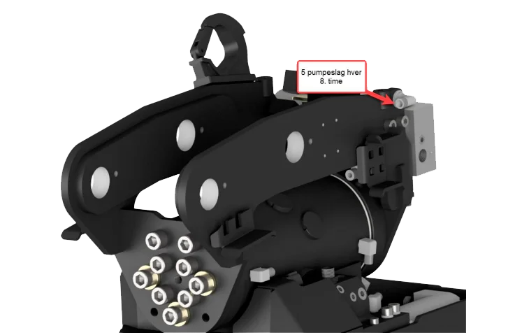
Smøreoversigt
For lubrication of the Compacttilt, it is recommended to use: Castrol Molub-Alloy 370-2 Lithium-based high-pressure grease with molybdenum disulphide (MoS2) EP additives in NLGI 2.
Spec.: -DIN 51502 KF2K-25 -ISO 6743-9 ISO-LXCCIB2
Greases containing graphite and copper must not be used. Always ensure that the lubrication nipples are free of dirt before lubrication is carried out.
Maintenance
During daily inspection and maintenance, check: ➢ Lubrication of lubrication points according to the overview ➢ Threads are intact ➢ Eyes and bolts are not broken ➢ No loose screw joints ➢ No cracks or fractures ➢ It is ensured that the tool holder is clean, mounted and clamped correctly ➢ Compacttilt Tiltrotator is correctly mounted between the carrier and the implement ➢ There is no hydraulic leak ➢ There is no grease leakage on hoses or in couplings
Connection of equipment
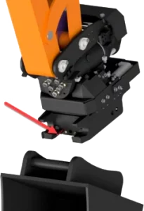
STEP 1
Before equipment is connected to the bucket attachment, it must be ensured that its locking pawls are
retracted, which can be seen by the indicator stick being pushed out.
(figure 5)
Figure 5
STEP 2
The equipment to be connected must be positioned so that the fork eyes of the bucket attachment can catch on.
The fork eyes of the bucket attachment are brought into engagement with the attachment shaft of the equipment.
(figure 6)
Figure 6
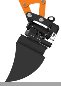
STEP 3
When the fork eyes of the bucket attachment have caught on, the tool is swung
in place so that it rests against the opening of the bucket attachment fork eyes.
The bucket lock is activated and the locking wedge is pushed out
(Figure 7).
The activation of the bucket lock can be seen by the indicator stick being lowered.
Figure 7
The machine is now ready for use with the connected tool.
Uncoupling of equipment
STEP 1
The shovel/equipment is brought down so that it rests against a supporting surface.
(Figure 8)
Figure 8
STEP 2
The bucket lock is unlocked by the operator until the indicator stick is driven out. This releases the locking wedge from the bucket shaft
(Figure 9).
Figure 9
STEP 3
With the bucket lock open, the tiltrotator is now moved away from the bucket/equipment (Figure 10).
Figure 10
The equipment is now disconnected from the machine.
Connection with CT-Oil
When using tools for use with CT-Oil, the following instructions must be followed to ensure correct coupling, as well as to ensure optimal service life of hydraulic couplings and mechanical components in connection with the CT-Oil system.
Please note that there must be min. 180 bar pressure on the bucket lock for the coupling to work.
Clean the hydraulic couplings at regular intervals on both the tiltrotator and equipment. Use possibly dust caps with longer breaks between uses.
During continuous use, a large amount of heat can develop on the hydraulic connections, so avoid touching them by them immediately after use.
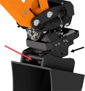
STEP 1
Before equipment is connected to the bucket attachment, it must be ensured that its locking pawls are retracted and the indicator stick is pushed out. The fork eyes of the bucket attachment are brought into engagement with the attachment shaft of the equipment (Figure 11).
Figure 11
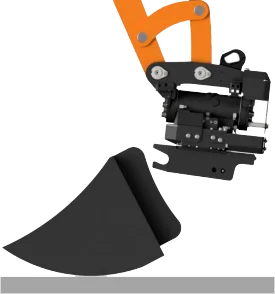
STEP 2
When the fork eyes of the bucket attachment have caught on, the tool is swung
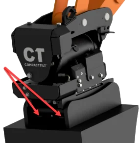
in place so that it rests against the open fork eye of the bucket attachment (Figure 12).
ATTENTION The connected equipment must rest with weight load on the point marked with arrows before the bucket lock is activated. This helps to extend the durability of CT-Oil the components.
Figure 12
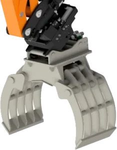
STEP 3
The bucket lock is activated. When the indicator stick is lowered, the equipment is connected and ready for use (Figure 13).
Figure 13
Decoupling of equipment with CT-Oil
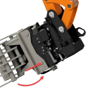
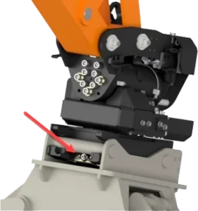
STEP 1
When disconnecting equipment, it is ensured, just like when connecting, that the equipment rests against the contact surface of the bucket attachment. Once secured
say this, the bucket lock can be disabled (Figure 14).
ATTENTION The connected equipment must rest with a weight load on it the point marked with arrows before deactivating the bucket lock. This helps to extend the durability of the CT-Oil components.
Figure 14
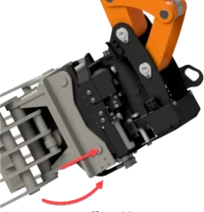
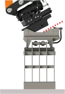
STEP 2
Place the equipment to be disconnected on a supporting surface and maneuver the tiltrotator clear of the equipment’s gripper shafts
(Figure 15).
ATTENTION Pay attention that the tiltrotator’s bucket attachment does not hit the equipment’s quick couplers when the tiltrotator is maneuvered freely.
Figure 15
The machine is now ready for use with the connected tool.
Use of quick change with hydraulic system
Control of installation
1. Check that the Compacttilt Rotator is working properly. 2. Check that no hoses or anything else is exposed to pinch, cut or stretch damage. 3. Check leaks. 4. Check that bolts are properly tightened [See carrier’s instruction]. 5. Check that there is no contact with the digging arm and the Compacttilt Rotator at full swing. 6. Ensure that the bracket fits the carrier [see machine sign]. 7. Ensure that the pin-lock is fully engaged and the indicator pin is correctly mounted.
NOTICE: Assembly and installation may only be carried out by workshops approved by the manufacturer. Do not make any changes to the assembly without the manufacturer’s permission. Workshops approved by the manufacturer are dealers with their own workshop, unless otherwise stated in the delivery of the Compacttilt Rotator.