Here is a short guide on how to treat and maintain the Compacttilt CTR10.
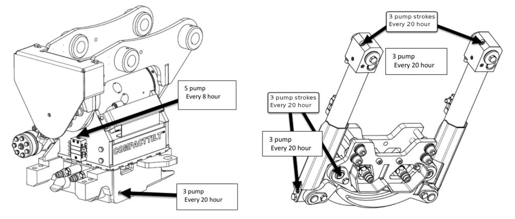
Lubrication overview
For lubrication of the Compacttilt, it is recommended to use: Castrol Molub-Alloy 370-2 Lithium-based high-pressure grease with molybdenum disulphide (MoS2) EP additives in NLGI 2. Spec.: -DIN 51502 KF2K-25 -ISO 6743-9 ISO-LXCCIB2 Greases containing graphite and copper must not be used. Always ensure that the lubrication nipples are free of dirt before lubrication is carried out.
Maintenance
During daily inspection and maintenance, check: ➢ Lubrication of lubrication points according to the overview ➢ Threads are intact ➢ Eyes and bolts are not broken ➢ No loose screw joints ➢ No cracks or fractures ➢ It is ensured that the tool holder is clean, mounted and clamped correctly ➢ Compacttilt Tiltrotator is correctly mounted between the carrier and the implement ➢ There is no hydraulic leak ➢ There is no grease leakage on hoses or in couplings
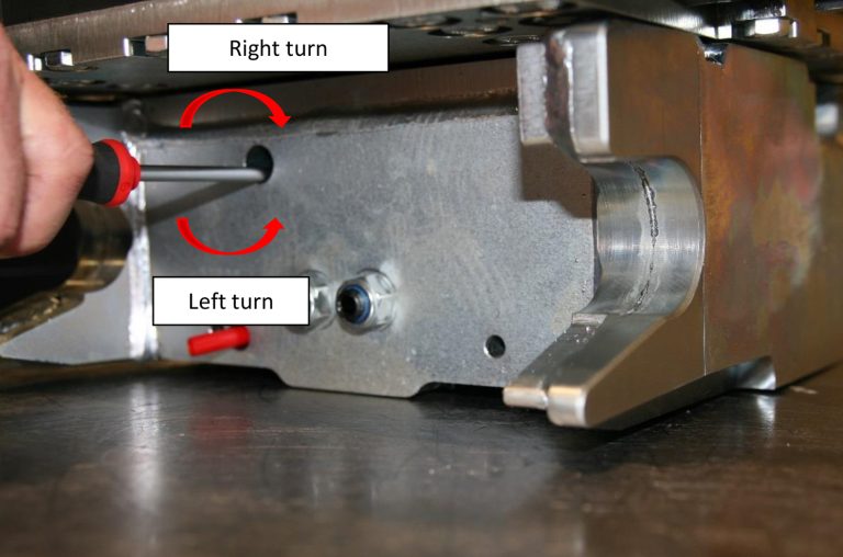
Manual change between gripper and ekstra oil outlet
Manual switching is performed with a 7 mm socket wrench with shaft
The extra oil outlet is always active when the claw is activated. Additional oil outlets can only be deactivated by removing the hydraulic coupling. The gripper can be activated / deactivated manually without disassembling the hydraulic coupling using this manual:
1. Turn the adjusting screw (right) in the swivel block highflow to stop, put the claw out of operation and only the extra socket is active (with highflow).
2. If the adjusting screw (left turn) is turned in swivel block highflow to stop, the gripper and extra oil outlet are active again.
Connection of equipment
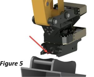
STEP 1
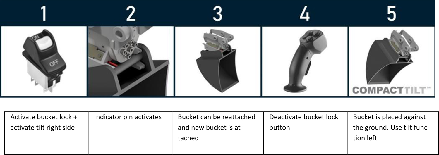
Before connecting the quick coupler gear, make sure that the quick-release locking pawls are retracted, which can be seen by pushing out the indicator pin.
(figure 5)
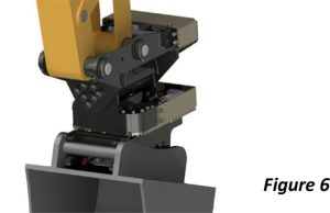
STEP 2
The equipment to be connected must be positioned so that the quick coupler fork eyes can catch.
The quick coupler fork eyes engage the coupling shaft of the equipment.
(figure 6)
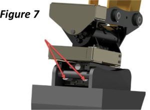
STEP 3
When the quick-release fork eyes have caught, the implement swings into place thus it abuts the open fork eyes of the quick coupler. The quick coupler is activated and the locking pawls are slid out (Figure 7).
The activation of the quick coupler can be seen by lowering the indicator pin.
The machine is now ready for use with the connected implement.
Use of quick change with hydraulic system
Control of installation
1. Check that the Compacttilt Rotator is working properly. 2. Check that no hoses or anything else is exposed to pinch, cut or stretch damage. 3. Check leaks. 4. Check that bolts are properly tightened [See carrier’s instruction]. 5. Check that there is no contact with the digging arm and the Compacttilt Rotator at full swing. 6. Ensure that the bracket fits the carrier [see machine sign]. 7. Ensure that the pin-lock is fully engaged and the indicator pin is correctly mounted.
NOTICE: Assembly and installation may only be carried out by workshops approved by the manufacturer. Do not make any changes to the assembly without the manufacturer’s permission. Workshops approved by the manufacturer are dealers with their own workshop, unless otherwise stated in the delivery of the Compacttilt Rotator.