Quick Guide - CT1

Here is a short guide on how to treat and maintain the Compacttilt CT1.

Maintenance

During daily inspection and maintenance, check:


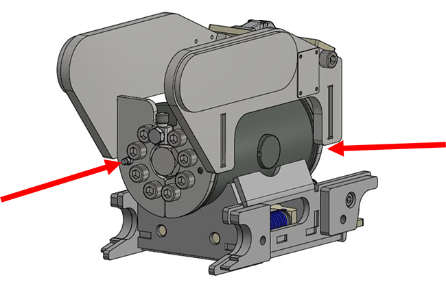
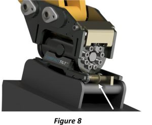
➢ Lubrication of end bearings. Course of action:
▪ Tilt all the way to one side and give 1-2 presses to the grease nipple at each end of the tilt.
▪ Tilt all the way to the opposite side, and also give 1-2 presses on the grease nipple at each end of the
tilt. Threads are intact


➢ Eyes and bolts are not broken
➢ No loose screw joints
➢ No cracks or fractures
➢ It is ensured that the tool holder is clean, mounted and clamped correctly
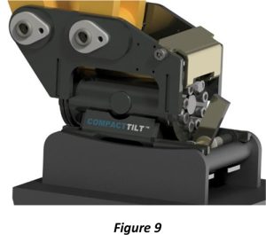
➢ The Compacttilt is correctly mounted between the carrier and the implement
➢ There is no hydraulic leak
➢ There is no grease leakage on hoses or in couplings

Lubrication overview

For lubrication of the Compacttilt, it is recommended to use: Castrol Molub-Alloy 370-2
Lithium-based high-pressure grease with molybdenum disulphide (MoS2) EP additives in NLGI 2.


Spec.: -DIN 51502 KF2K-25
-ISO 6743-9 ISO-LXCCIB2


Greases containing graphite and copper must not be used.


Always ensure that the lubrication nipples are free of dirt before lubrication is carried out. 

Use of semi-automatic quickchange

STEP 1

Before equipment can be connected to the quick coupler, the change locks must be in an unlocked position. This is done by mounting the supplied release tube on the quick-release actuation arm

(figure 5)

STEP 2

The release tube is pushed down until it stops, bringing the locking plate to an unlocked position (Figure 6).The release tube can now be removed and the lock remains in the unlocked position.

(figure 6)

Connection of equipment

STEP 1

The equipment to be connected must be located so that the Compacttilt’s fork
eyes can catch.

The forks of the Compacttilt engage the coupling shaft of the equipment

(figure 7)

STEP 2

When the equipment is swung into place on the Compacttilt’s switch, the equipment’s shaft strikes the shutter release lever, thereby activating the forest lock.

(figure 8)

STEP 3

The machine is now ready for use with the connected equipment.

(Figure 9).

Use of quick change

Control of installation

1. Check that the Compacttilt is working properly.
2. Check that no hoses or anything else is exposed to pinch, cut or stretch damage.
3. Check leaks.
4. Check that bolts are properly tightened [See carrier’s instruction].
5. Check that there is no contact with the digging arm and the Compacttilt at full swing.
6. Ensure that the bracket fits the carrier [see machine sign].
7. Ensure that the pin-lock is fully engaged and the indicator pin is mounted correctly.

NOTICE: Assembly and installation may only be carried out by workshops approved by the manufacturer. Do not make any changes to the assembly without the manufacturer’s permission. Workshops approved by the manufacturer are dealers with their own workshop, unless otherwise stated in the delivery of the Compacttilt.

Download the full user manual